Contents

My TYT THD9000 started to exhibit some strange behavior, after transmitting it sometimes needs half a second to switch back to receive. So I was in the market for a new APRS radio and came across the Retevis RT98.
Add to that that my doctor wanted me to reduce my computer time because of a chronic pain in the arm, it was a good time to fire up the soldering iron ! In the end it took me a couple of weeks to write this article out of my notes.
Enough talking about health issues. This is quite a lengthy article but the road to completion of this project was quite bumpy. I needed to replace the original microphone cable to get the signal needed for APRS operation. At the end I have a new APRS mobile system even with voice alert capability !
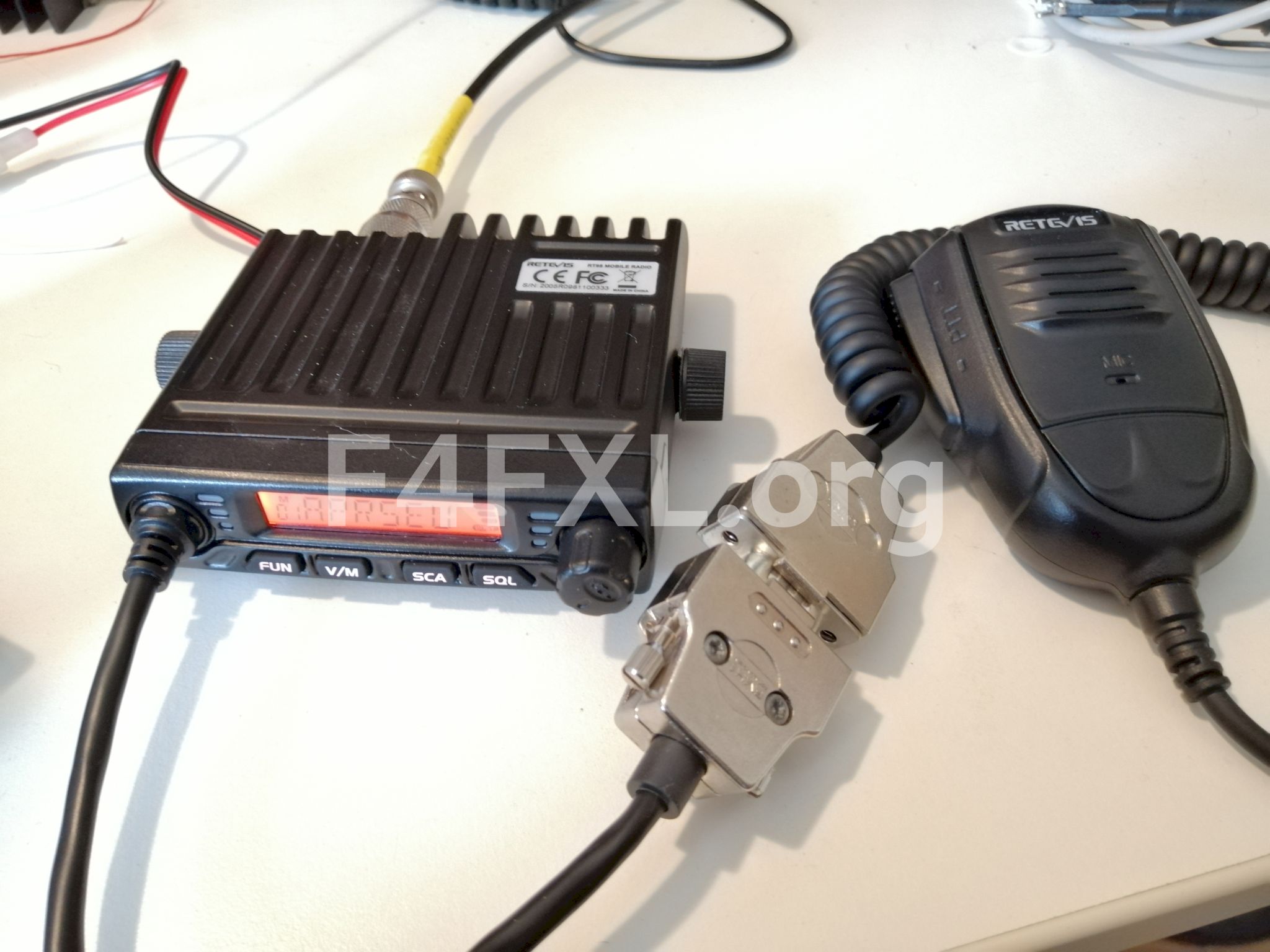
A brief review of the Retevis RT98
The Retevis RT98 is a mono band radio available in VHF and UHF. Of course for APRS I went for the VHF version. It is actually manufactured by Anytone as Anytone AT-779. It is sold globally under different brands, in Europe mainly as CRT Space. Somehow it is quite difficult to get it under the original Anytone brand.
The RT98 has no way of changing channels other than through the microphone hence the lack of a proper microphone connector. As we will see later this was the tricky part of this project.
Despite being advertised as an amateur radio, the RT98 that got delivered to me lacks a true VFO! Earlier version had a VFO as it can be seen in various Youtube videos. The V/M key only toggles name display or frequency display. I got in touch with Retevis support and they said will go check with the factory… After thinking it through for a while i decided to keep the radio, since it will be used 99% of the time for APRS I could live without a VFO. Fun fact : all the channels parameters power, tone, etc can be changed through the menu. This makes the removal of the VFO even more baffling.
Modifying the RT98
Now it is time to contemplate your radio’s warranty as you’re going to void it as soon as you decide to follow instructions given in this article. As always, if you break something, injure yourself or someone it is your sole responsibility.
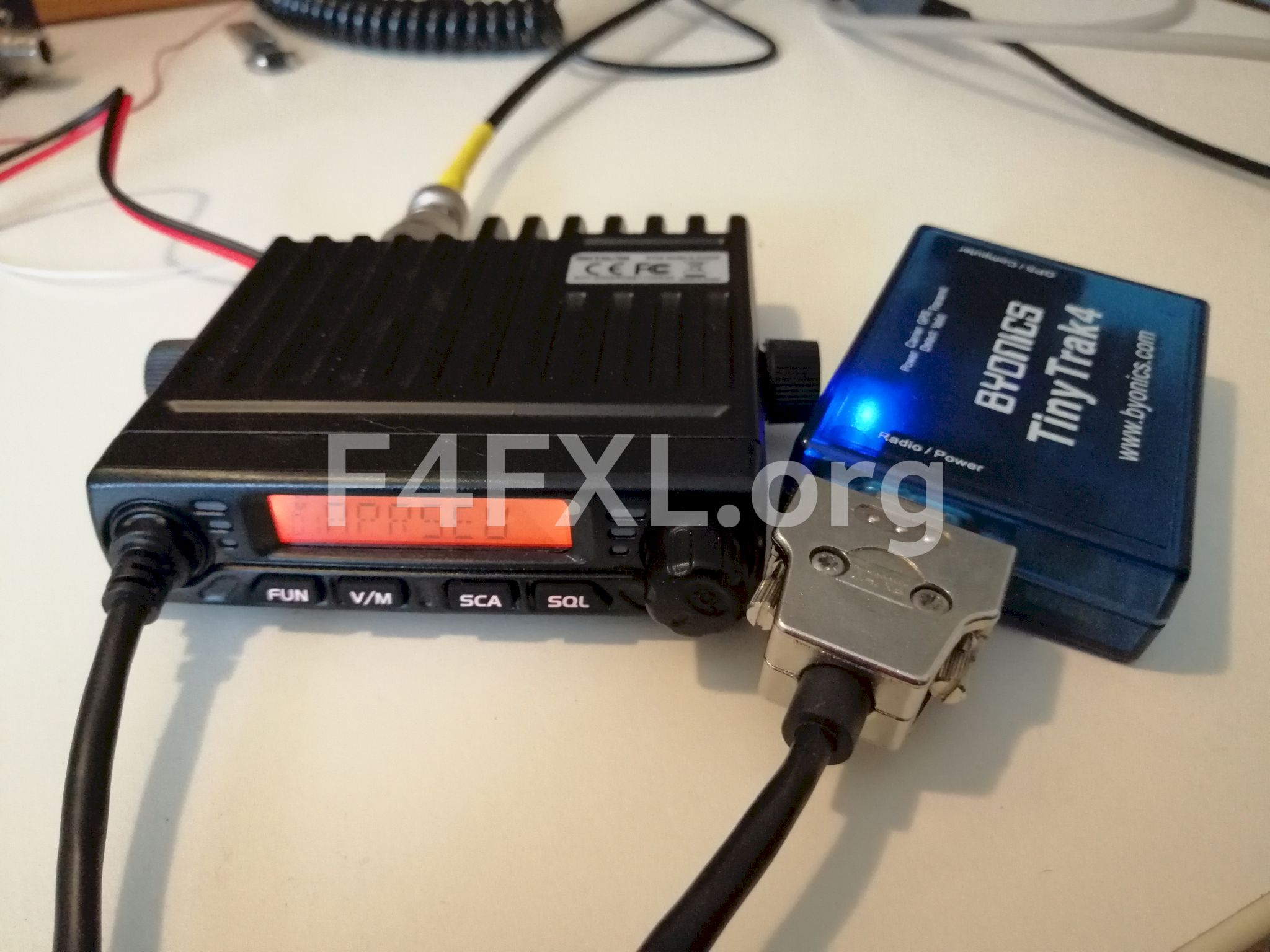
I wanted a neat setup where the Tinytrak 4 gets all of its signals and power from one unique cable straight from the radio. Long story short the Tinytrak 4 will need to take the place of the microphone.
The original microphone cable only has 4 wires : mic, ptt, up/down and ground and we need 6 wires : mic, ptt, receive, up/+down, +12V. We need to replace the 4 wires cable with a 6 wires one. We will fit the microphone with a connector in case we need to change channel at some point (you remember the microphone is the only way to change frequency).
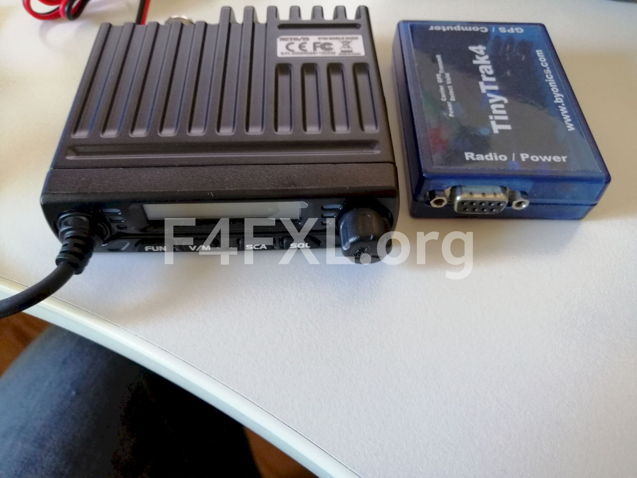
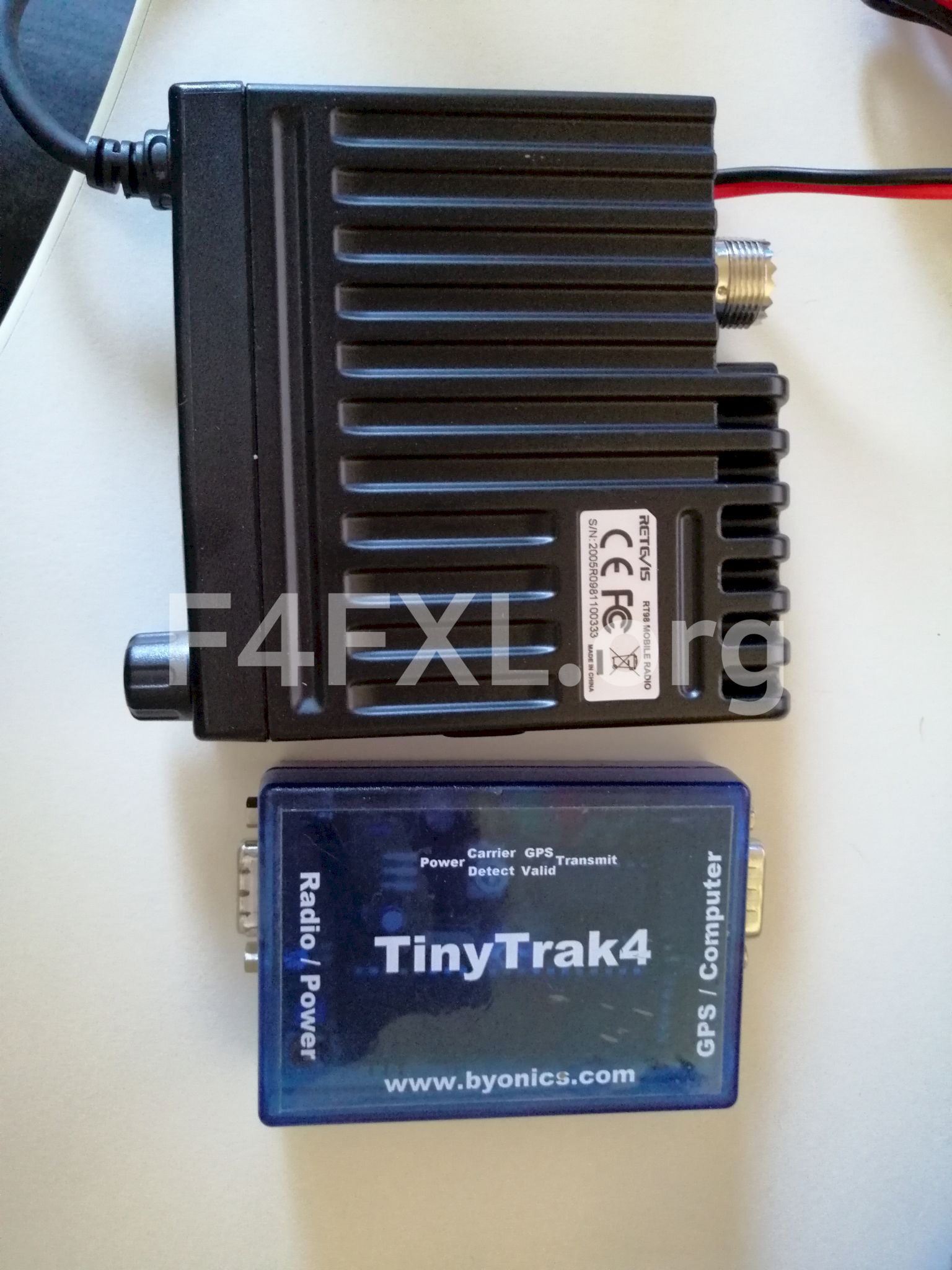
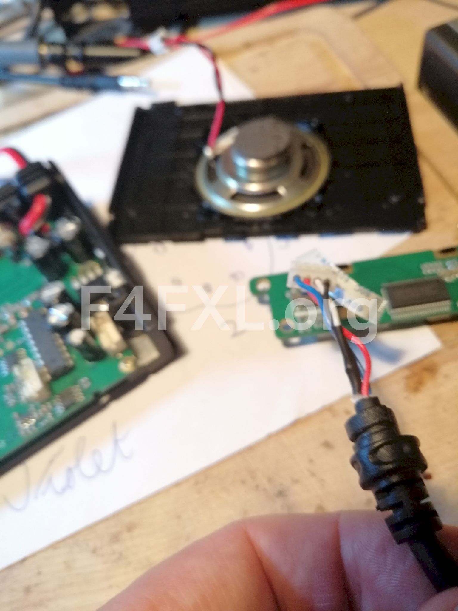
So off we are to disassembling the radio ! Unfortunately I did not take pictures at each step, that’s why I grouped all the pictures I made at the end of the article with a description. If something is unclear feel free to ask in the comments.
Disassembling the radio
- Remove the 4 torx screws holding the speaker lid in place
- Carefully disconnect the speaker from the main board
- Disconnect the white connector going to front panel rotary knob
- Disconnect the white microphone connector
- Carefully disconnect the ZIF cable going to the front panel
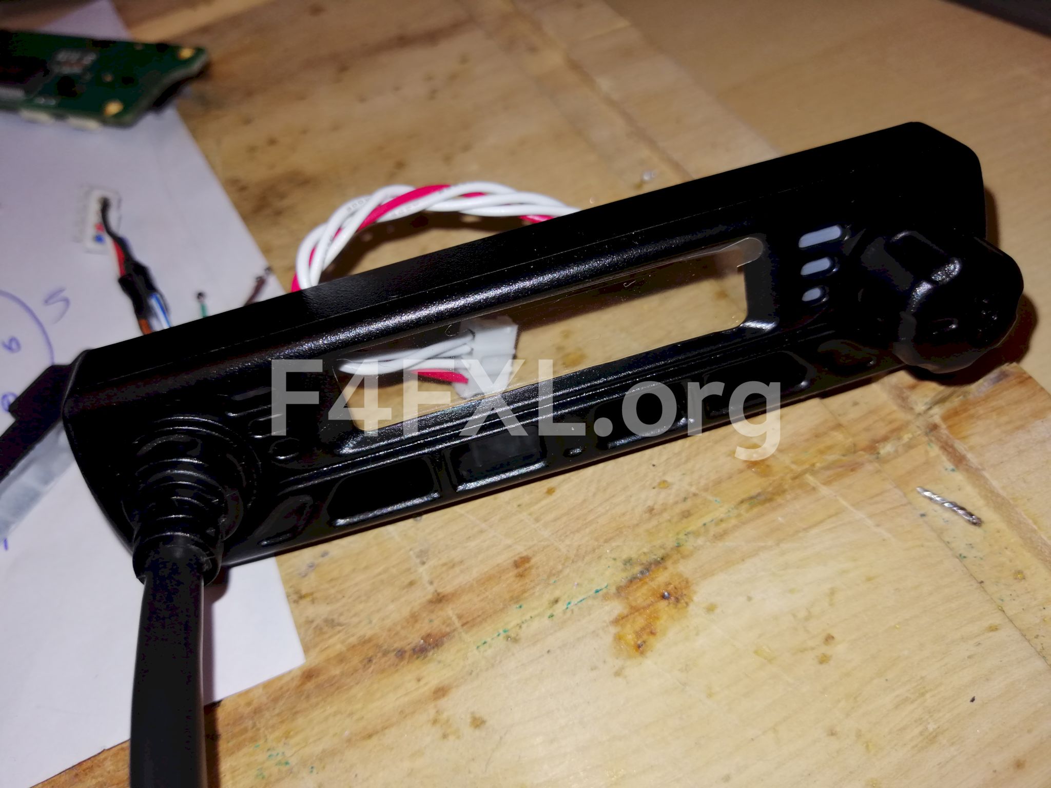
- Remove the two screws holding the front panel
At this point you should have the front panel lose from the radio with the microphone dangling from it.
Let’s remove the microphone from the front panel.
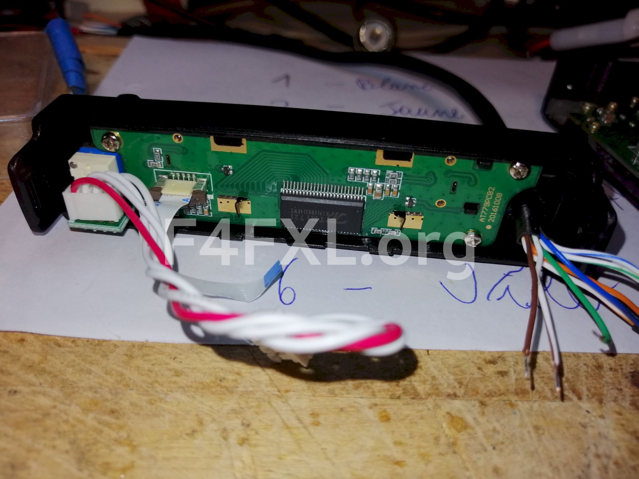
- Remove the front panel PCB by removing the 4 screws and store it in an ESD safe container. A ESD bag is OK.
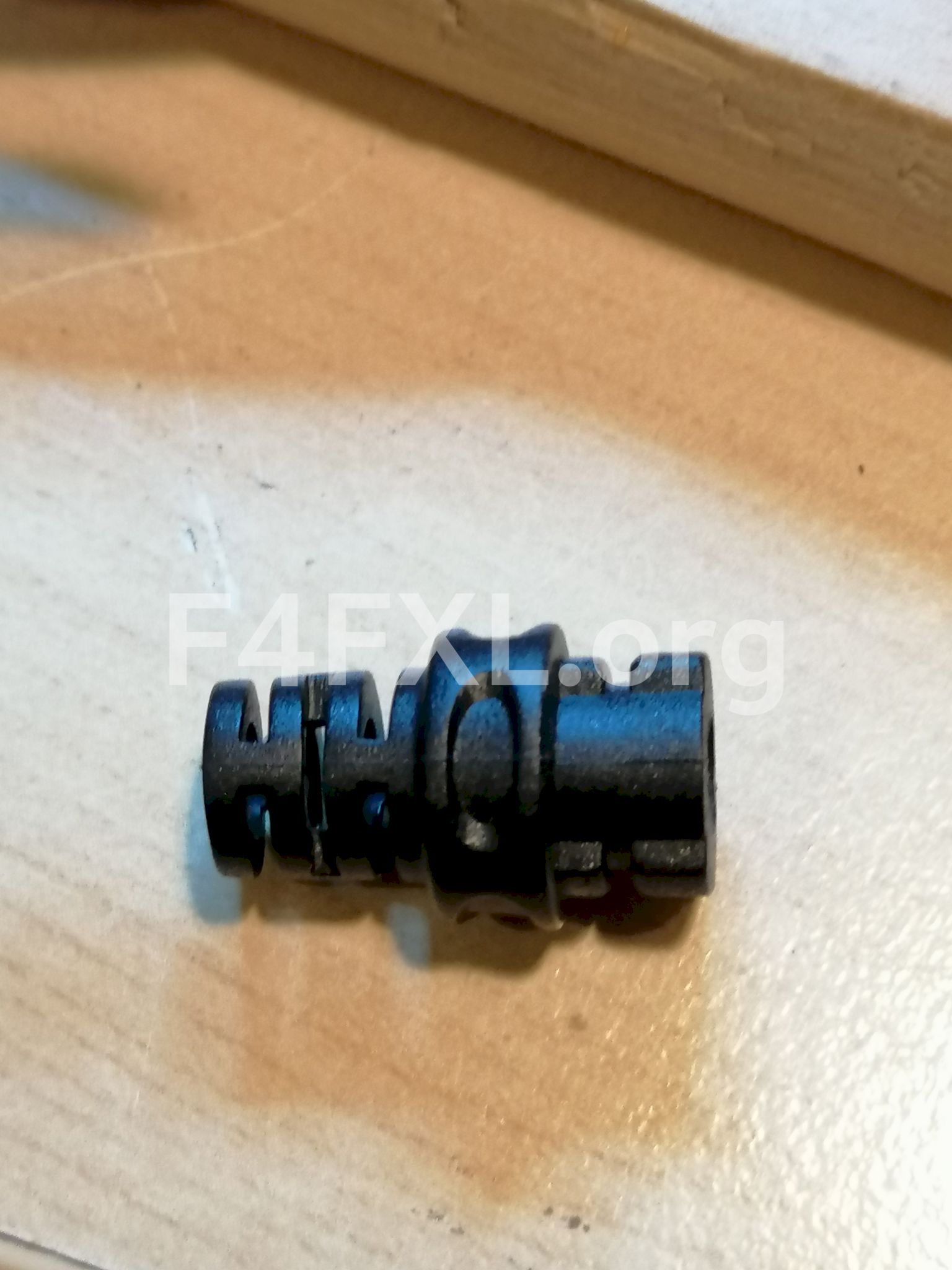
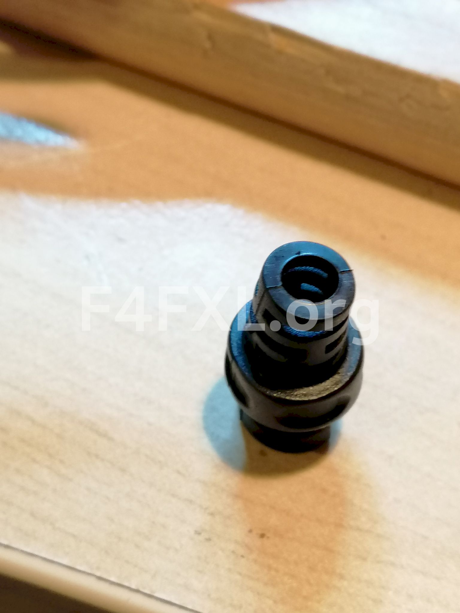
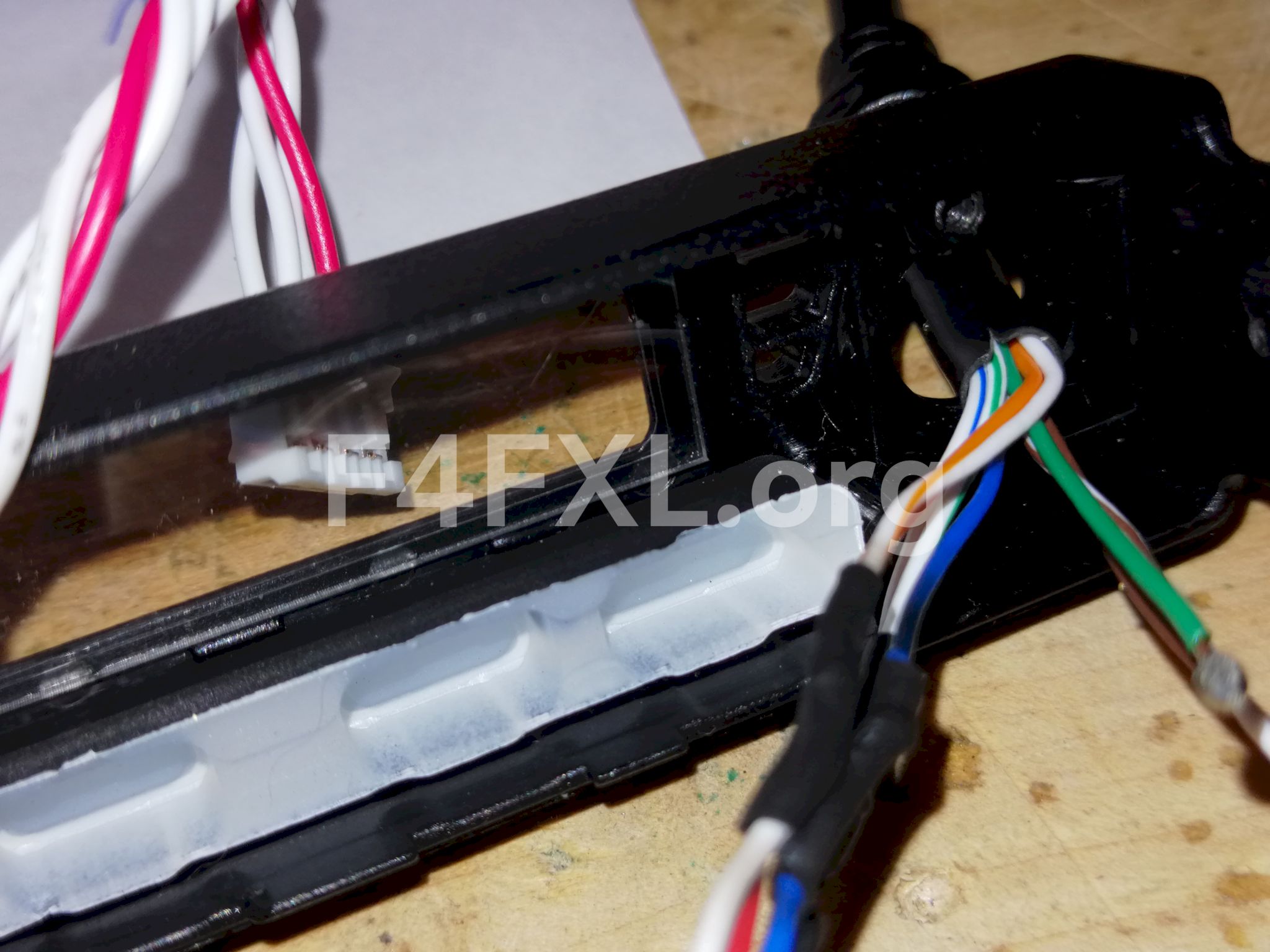
- Closely look at where the microphone cable goes through the panel. You’ll notice a small metal clip holding it into place. Using a flat screw driver gently push it toward the display and the microphone cable should come lose. The white connector can be removed through the hole so you have the front panel on one side and the microphone on one side.
- Now take a deep breath an cut the microphone cable as close as you can to the cable-sleeve as you can. We are going to reuse the white connector to the main board so make sure to leave enough wire length.
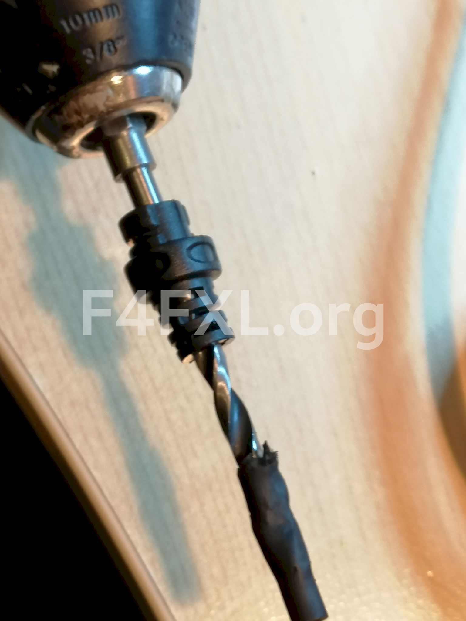
- To recover the cable sleeve remove all of the wires from the cable. Use a 3 to 4mm drill bit and slowly pass it through the sleeve, at some point the remaining of the cable should come lose from the sleeve.
Replacing microphone cable
- Find a 6 wire cable with a maximum diameter of 4mm and about 20cm length to fit through the cable sleeve. I ended up using a black network cable. It is quite stiff but fits nicely through the sleeve.
- Fit the original cable sleeve onto your new cable
- Cut your cable wires keeping the ones you will use for RX audio and 12vapproximately 2cm longer than the others.
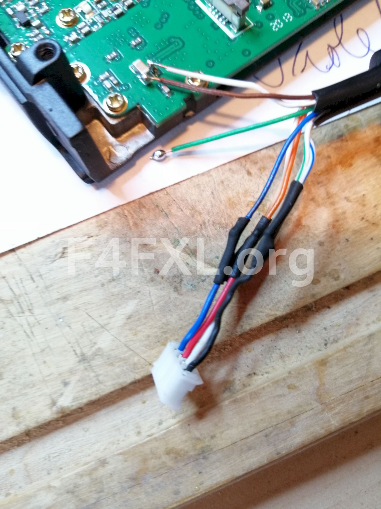
- Solder your new cable to the original microphone connector, only the following signals are present on the microphone.
| Wire Color | Signal |
|---|---|
| White | TX Audio |
| Blue | Up/Down |
| Black | Ground |
| Red | PTT |
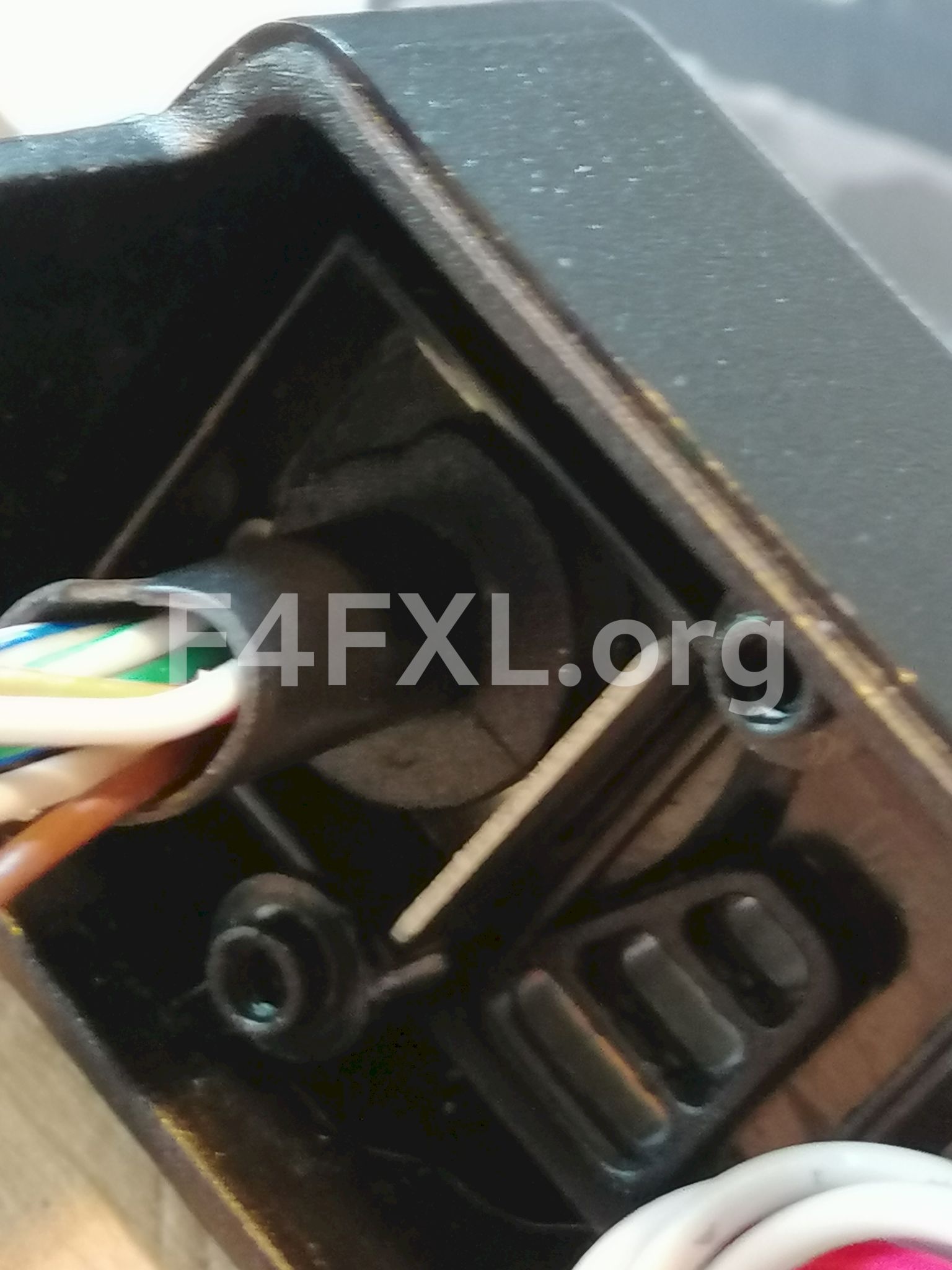
- Pass the connector through the front panel and reinstall the metal clip holding the original sleeve in place
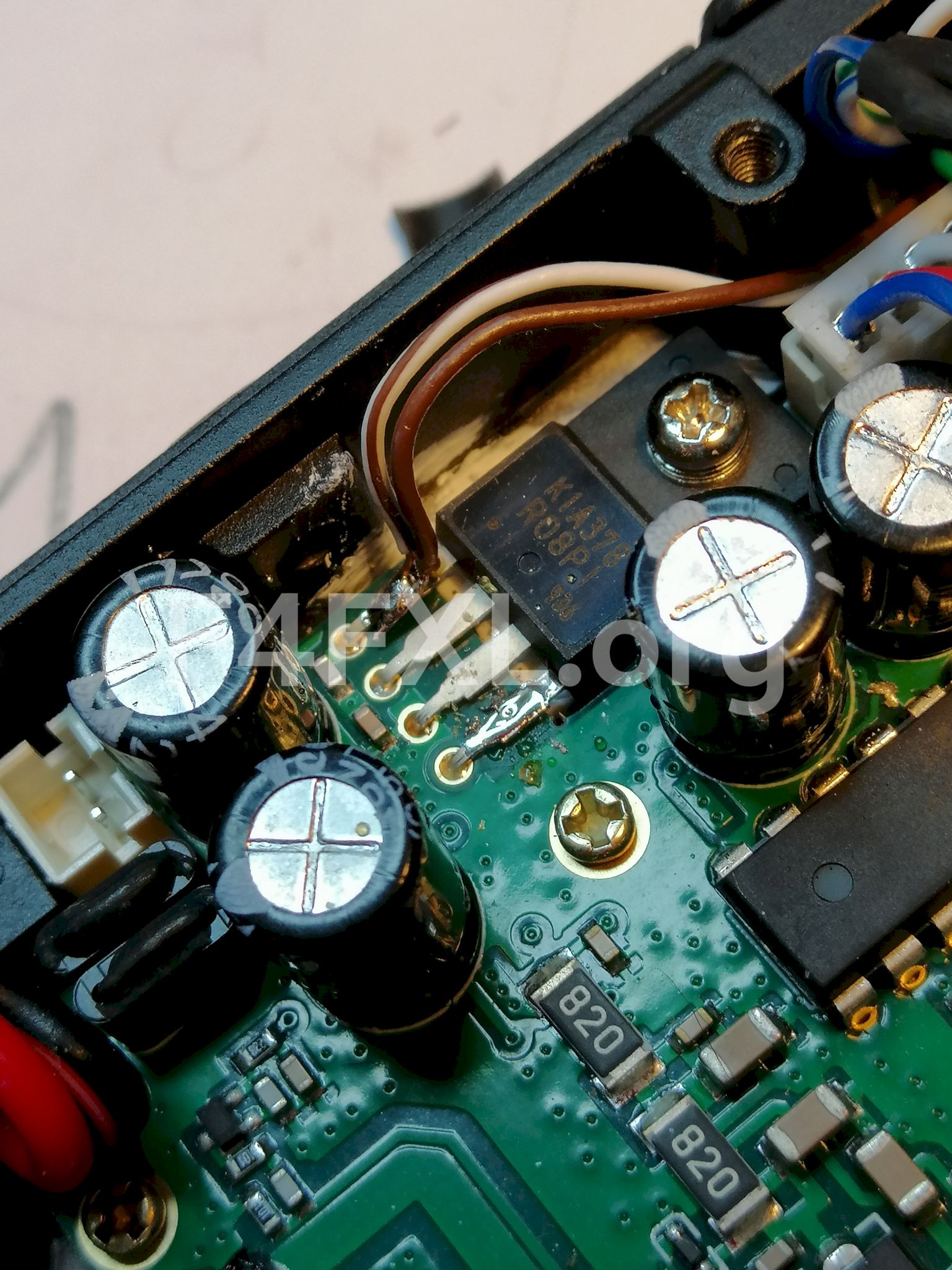
- Solder +12V wire to the voltage regulator. 12V is always present, regardless if radio is powered on or not.
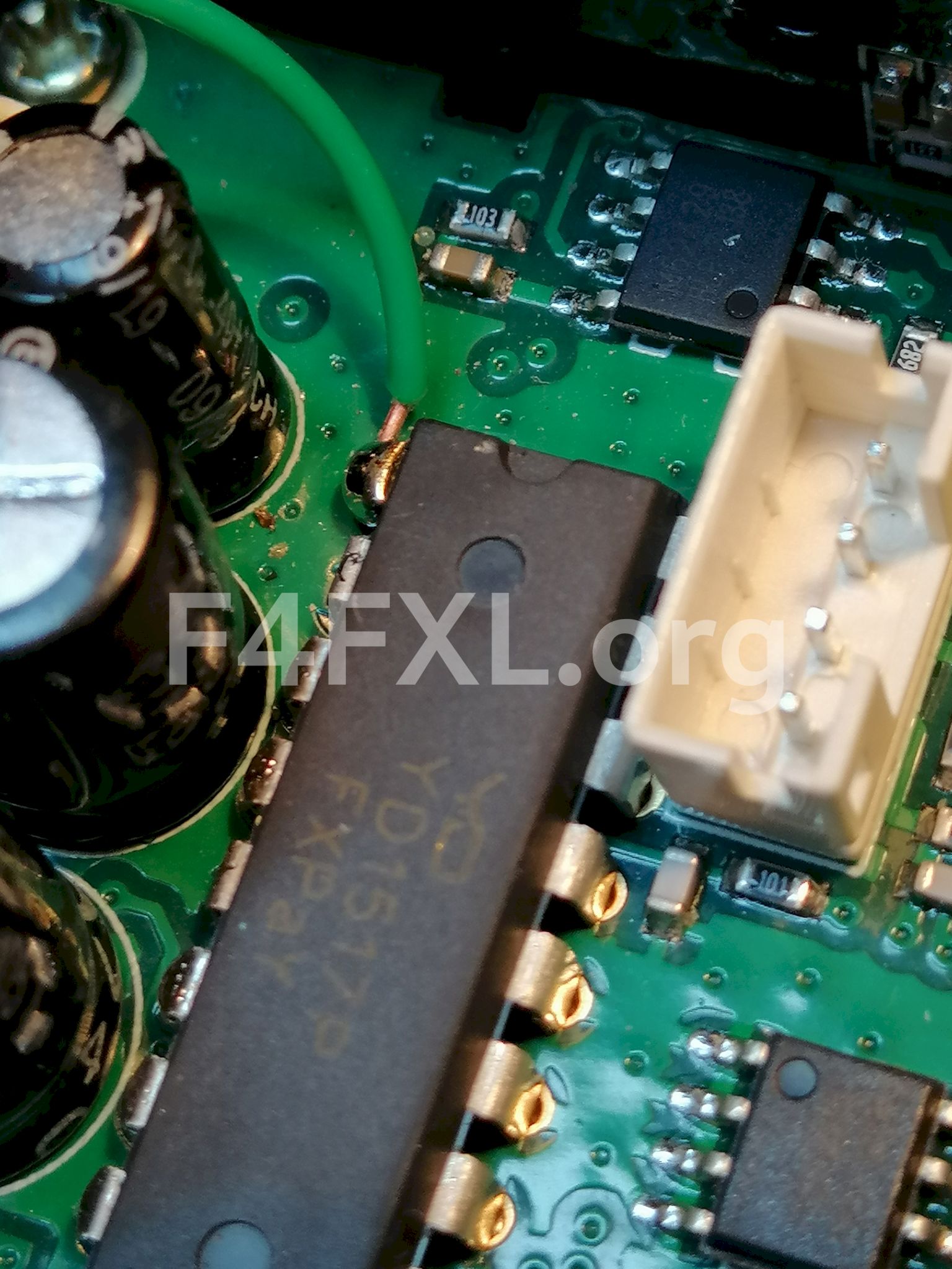
- Solder RX audio to pin 1 of the only non SMD integrated circuit. Use caution as to not overheat the IC! The audio signal here is unsquelched nor affected by CTCSS which wil allow us to use voice alert !
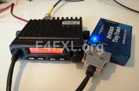
Installing a DB9 connector for the Tinytrak 4 and recover the microphone
On the other end of your new cable install a male DB9 connector. We will use pin 9 for UP/Down as it is not used on the TT4. On the microphone cable install a female DB9 connector this way we can reuse the microphone when needed.
The table below shows the wiring for the the Tinytrak 4 and the original microphone.
| DB9 Pin number | Tinytrak 4 | Microphone Cable |
|---|---|---|
| 1 | TX Audio | White |
| 2 | ||
| 3 | PTT | Red |
| 4 | ||
| 5 | RX Audio | |
| 6 | Ground | Shield |
| 7 | +12V | |
| 8 | ||
| 9 | Up/Down | Blue |
Putting the radio back together
This is straightforward, however some care is needed to not damage the ZIF cable. If all is fine you should have the front panel without its PCB but your new cable installed.
- Put the front panel PCB back in place.
- Attach the front panel back to the radio body using the screws. Be careful not to pinch the ZIF cable or the volume knob cable.
- Reconnect the ZIF cable, be sure to push it up to the end into the connector. Any malfunction of the radio after on might be caused by an improper connection of this cable.
- Reconnect the volume knob connector.
- Reconnect the speaker and put the speaker lid back into place
Levels and configuration
Receive levels
- Adjust volume on the radio to 8. Setting the squelch is irrelevant as we are taping the squelch from an unsquelched signal source.
- On the Tinytrak 4 set the following values :
- RXAMP: 27
- CDMODE: TONES
- CDLEVEL: 20
Transmit Levels
- Adjust Mic Gain to 8
- On the Tinytrak 4
- TXLEVEL: 50
- TXTWIST: 28
Configuring the Radio
Since Retevis thought it’d be wise to drop the VFO, I programmed the channels I need as follow.
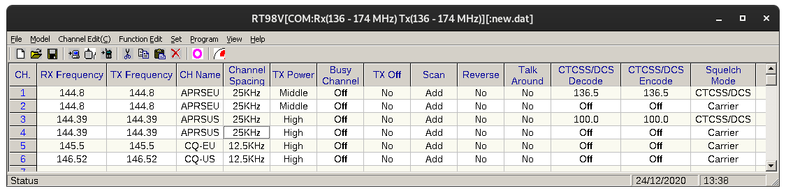
Channel 1 and 3 are for use with voice alert respectively in Europe and US. The use of CTCSS while keep the speaker quiet unless a matching tone is received, this means you are in simplex reach of another station. This is how voice alert works. If you are not going to use Voice Alert use either channel 2 or 4. In this case you will need to plug a 3.5mm jack into the speaker jack to avoid hearing all the packets.
One might wonder why I am using 25kHz (Wide) channel bandwidth. Well it happens that some sysops in my area think 25kHz is still a thing. Using 25kHz the TT4 will decode both 25 an 12.5kHz signals. The transmit levels we have configured will roughly fit the 12.5kHz channel bandwidth.
You can download the file containing the channels here.
Conclusion
We now have a nifty compact APRS system, if you have bluetooth enabled Tinytrak 4 it is a perfect setup for long road trips to be completely APRS ready and off the grid. You will see station close to you and if you are on voice alert you do no need to regularly check the display, you will be warned whenever another station is nearby.
Pictures

Pingback: Retevis RT98 – Quick Overview – Ham Radio? GMRS Radio (Here Come The COMMENTS!!) –
Thank you for your work on this. I put a DE-9 connector on the cable to interface to a USB-RIM Lite: http://www.repeater-builder.com/products/usb-rim-lite.html
I clipped the blue wire and reused it for the RX audio line as I did not need to adjust the frequency on this one, however looking at the microphone, it does not appear that the blue wire is connected to anything.
Instead, there are resistors between PTT (red) and ground, 2.2K Ohm for down, 3.9K for up, 1% tolerance.
I see mounting holes for resistors that would go between the buttons and the blue wire, so it may be used on a variant or maybe there was a manufacturing change.
Hi Ben,
Thank you for your comment, sorry I was held up by the spam filter because of the link.
I did not know about this interface. What will you use it for if I may ask ?
I have to admit I did not investigate if all the wires are really used as I wanted to route the power through the cable and as a matter of fact still need one wire more. But if someone wants to keep things easy, using blue for the audio and externally wiring the power for the Tinytrak might be the way to go.
I checked my microphone and on mine to blue is connected to nothing.
Hi,
The interface is designed to connect to an Alinco DR-135. I use it for APRS with Direwolf on a Raspberry Pi. I wanted to replace the DR-135 with something a little smaller as it’s mounted in my car, and came across your page while looking for more information on the RT98. It seems pretty useless for general voice use with the lack of VFO, but perfect for packet. Thank you again for your thorough write-up, it was extremely useful.
Hi Ben,
Thanks for the feedback. This is great to know! I am happy the article turned out to be useful to you.
Take care,
Geoffrey
Is there enough room in the face, where the original mic cable comes through, for an RJ45 bulkhead connector? I’m thinking an RJ45 male to 3.5mm TRRS cable could be used for connecting a Mobilinkd TNC, as well as a male connector added to the factory mic so you can quickly swap between voice and data or change channels.
Hi Jimmy,
I did not have any chassis RJ45 to test with. But I guess there is enough room to fit one. Yet I think it’ll be difficult to attach it firmly….
Hi, did you ever get a response from Retevis regardi g the VFO, I have the sane problem, altgough the manual clearly states there is a VFO mode and it was advertised as having a vfo mode when I purchased it they refuse to help me with it, I got the uhf model and it’s pretty much useless to me without the vfo mode. Very frustrating.
Hi, they never came back to me. This is a real shame as the radio is pretty good from an RF point of view.