Contents
Introduction
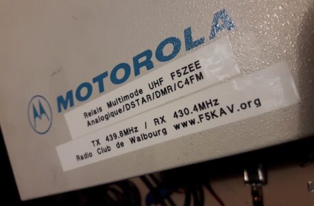
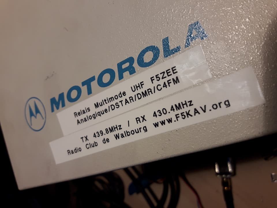
I came across a Motorola R100 repeater, those were very capable low to mid duty analogue repeaters in the mid 80s up to the 21st century, yet some of them are still in commercial use! What follows is more or less a memo on how I converted it for digital (Dstar and DMR) use and eventually analog/digital use. I got awesome results in DStar, pretty good results in DMR but Fusion is not so good as I did not have a Fusion radio to test. There is a huge amount of information available online, especially on Repeater Builder, they even have information on DStar interfacing however the latter did not work for me. What follows applies to the UHF variant of the repeater, for VHF your mileage may vary. This worked for me and might not work for your particular case.
Disclaimer
You are following this article at your own risks. I am not responsible for any loss, damage or anything bad happening to you or your belongings. Be sure to read EVERYTHING before you get started, especially the prerequisites paragraph. Please read all the literacy on Repeater Builder as it has good information about using the R100 as a higher duty repeater : cooling etc…
USE A 50OHM LOAD ON THE TX OUTPUT ALL THROUGH THIS PROCEDURE !
Prerequisites
This modification is not a plug’n’play thing and you need a couple of things before you get started:
- The service manual, get it from here.
- An oscilloscope, do not even think having descent result without this !
- DStar radio or a HF generator capable of outputing a square wave modulated FM signal. I used a Dstar radio.
- A receiver with a discriminator tap or a SDR radio capable of displaying demodulated FM signal without any de-emphasis
- SMD soldering/desoldering tools
Notes on repeater programing
Program the repeater using CTCSS, NOT carrier squelch. This to avoid unwanted TXing on noise as we will keep the legacy Motorola logic untouched.
Receiver
Tuning and modifying
The receiver needs to be adjusted as per the service manual. Once done, there is an additional step specific to digital : Adjusting the IF group delay in the receiver. Connect your oscilloscope to pin 4 of U551, U551 is located on the command board. Using your HF generator generate a FM signal modulated with a 4kHz square wave at 2.5kHz deviation, or simply use a DStar radio. Monitor the signal on your oscilloscope an adjust L51 on the RF board to make sure the signal does not exhibit any ripples on the top and bottom part i.e. the signal must be as flat as possible on the top and bottom.
There is a low pass filter at the discriminator output, you need to modify it as follow. Depending on the MMDVM board you are using you might want to completely remove any filters on the board as cascading filters is not a good practice. 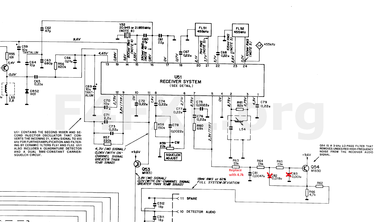
Next step is to reduce the gain of U551A, this might not be necessary depending on the MMDVM board you are using. Try adjusting the RX potentiometer on your MMDVM board so that you get approximatively 0,7v pp at the MMDVM A/D converter input. With my MMDVM board, the voltage was far to high, causing lots of ADC overflows, I could have modified the MMDVM board itself but went the route to modify the receiver. This is achieved by reducing the gain of U551A. To reduce the gain of U551A replace R551 with 6.5k.
Interfacing with the MMDVM
Solder a 500 Ohm to 1kOhm resistor on pin 4 of U551 and connect it to the connect RX input of your MMDVM. Use shielded wires or twisted pairs, with the ground connected as close as possible to U551.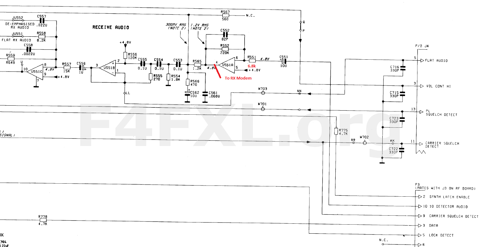 From this point you should be able to receive DStar without any issues.
Transmitter
Alignement
Align the transmitter as per service manual. No additional steps are required, this will be done at alter stage.
PTT Interfacing
On the logic board locate the “Intercom” switch. Solder a wire on the upper side of the switch and run it to the PTT output of your MMDVM. Done.
Discard analog signal, and TX signal interfacing
To ensure clean transmitted signal we have to discard the analog signal path (we might restore it later). On the command board, cut the trace that goes from R610 to pin 1 of the connector that goes to the TX RF Board. From this point on, analog operation is no longer possible. I soldered a wire directly on the pin 1 of the RF connector that goes to the RF board. Use twisted wires or shielded wire. You can get a ground on pin 8 of the connector.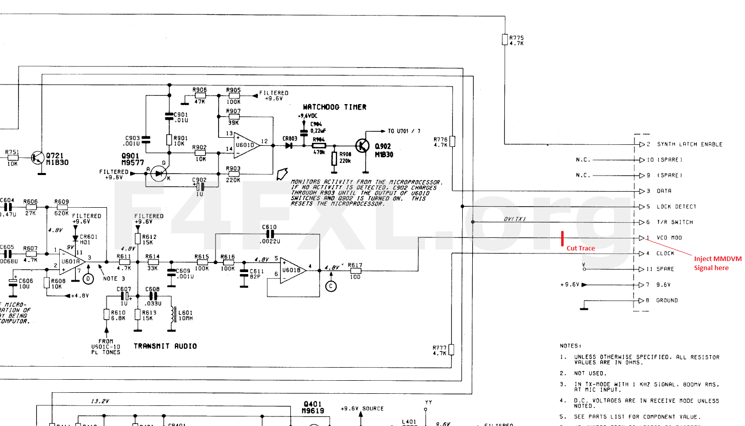
Front this point you should be able to use MMDVMCal in the DStar mode and toggle TX/RX.
Adjusting TX signal
Connect your oscilloscope to a receiver with a discriminator tap. Tune the receiver to the output frequency of your repeater. Transmit on your repeater’s output frequency using your DStar radio, and take note of the signal’s peak to peak amplitude. This amplitude actually reflects the received signal’s excursion.
Using MMDVMCal transmit using the DStar calibration mode. Monitor the repeaters signal using your oscilloscope through your other receiver and adjust R302, R305 and the MMDVM tx level. Start with R302 until you have the same peak to peak amplitude than with your DStar radio. You might also need to adjust the level on your MMDVM. Once you have the same levels adjust R305 to get a signal as clean as the signal of your DStar radio i.e. no ripples.
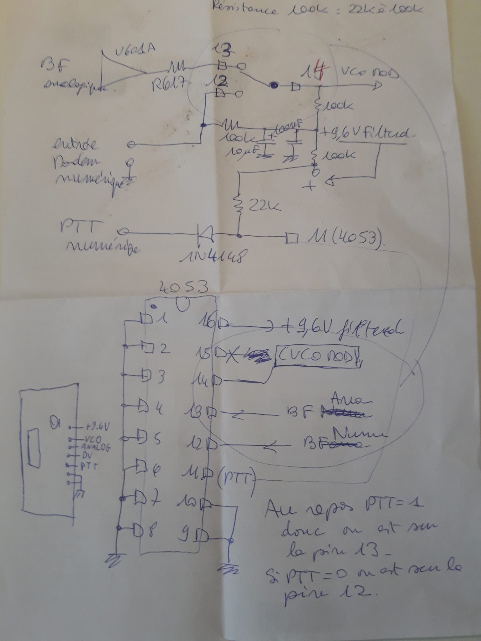
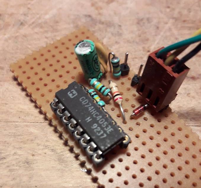
Restore analog
As we kept the whole legacy Motorola logic intact, the repeater will still respond to any CTCSS signal and go into TX, unfortunately since we cut the trace feeding the analog signal to the VCO you will not transmit anything. After chatting on the air with Jean-Matthieu F5RCT he came with the idea of this small audio switching board. Basically analog will be fully functional, yet any digital will have priority over analog. At a club meeting he came up with this simple schematic around a 74HC4053. Both analog and MMDVM signals are fed into this board. The PTT of the MMDVM is also applied there, as soon as the MMDVM triggers PTT the audio fed into the transmitter is switched to the MMDVM signal. Adjust the analog audio level using R820 on the logic board.
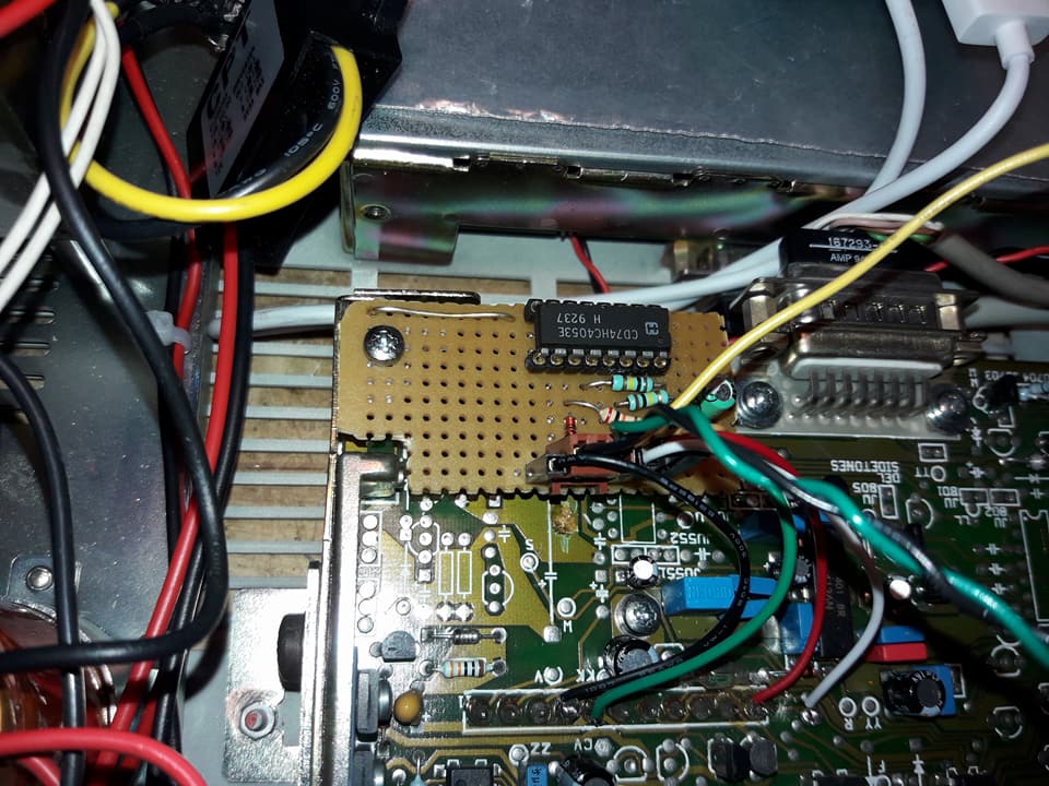
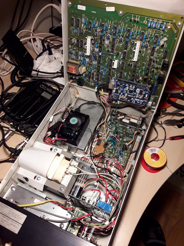
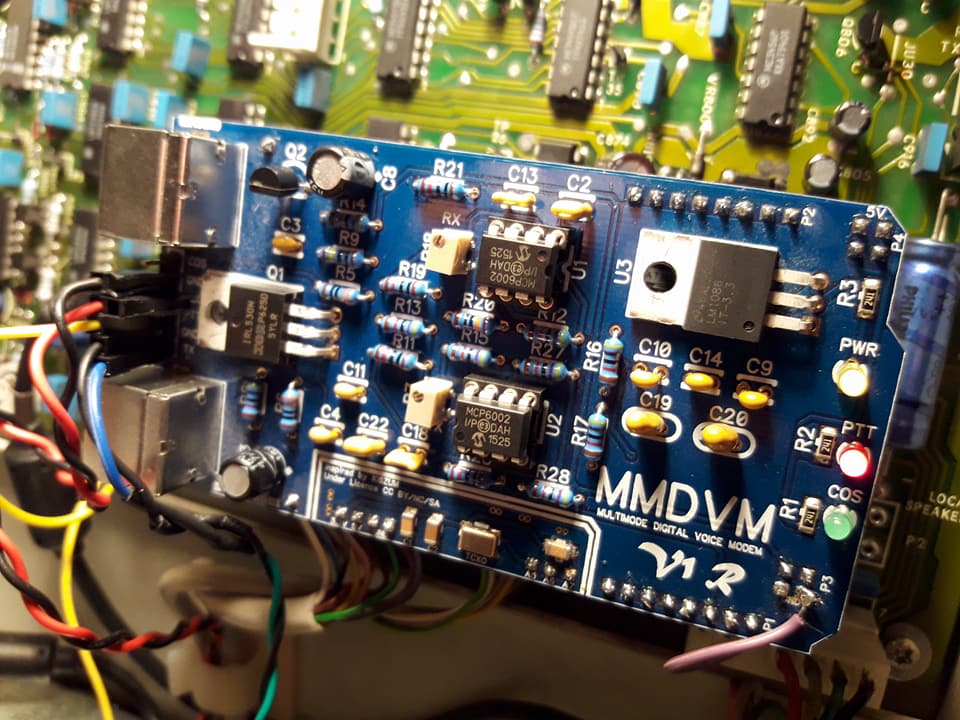
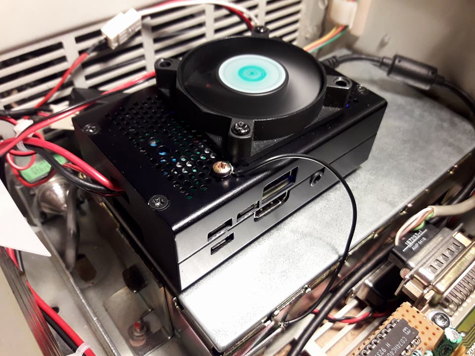
Everything in the box
There is plenty of room inside the R100 to put the MMDVM board and the Raspberry-pi. I am using a Pi3 powered with a StromPi 2, be sure to use a metal case to provide basic shielding. The Pi is mounted using adhesive Velcro, a short wire make sure it is grounded. The MMDVM sits where the 5 tons signaling board of the repeater used to be, perfect fit.
Thanks
I would like to give a big thanks to all the people who helped me throughout this project :
- Stéphanie, my wife for supporting my nerdiness 🙂
- Jean-Matthieu F5RCT for all his good advices and the audio switch board
- Mathieu F4GDL for pushing me to get this project started
- Christophe F1TKE for his thoroughly testing of the repeater and providing valuable feedback
- Valentin F4HTP for his help putting everything in the box
- Arnaud SWL for his help fitting a DS18B20 temperature sensor on the PA
- The nice guy who donated the R100 🙂
- Toufik F0DEI for the MMDVM Board

Would a scope be needed for DMR operation setup. Not interested in DStar.
Hi Gary,
Yes it would be needed. If it does not do DStar correctly it wont do DMR neither.
Pingback: Buggy Icom ID-51 and ID-5100Firmware | | F4FXL